For most homeowners one look inside a central heating wiring
centre is enough to convince them to get the professionals in, which is a shame
because the most common failures in a central heating system are the pump and
the motorised valves and these are both wired back to this complicated,
spaghetti like, mass of wires.
Fortunately, things are getting easier. For pumps it was
never that difficult, they only have 3 wires: live, neutral, earth and if you
can’t manage 3 wires you really have to ask yourself if you should be doing
this at all. That said, only good can come from keeping people away from the
wiring centre, so these days the cable on most pumps comes with a kettle-like
connector that can just be detached and plugged in to the new pump, the proviso
being that you replace like-for-like.
For motorised valves, especially 3-port valves, it is a bit
more intimidating. A 3-port valve has 5 wires: Neutral (blue), Earth (yellow
and green), Hot Water Off (grey), Central Heating On (white) and Switched Live Out (orange).
Fortunately, the number of wires and their colours is pretty much
a standard across the industry so you can replace a 3-port or 2-port valve from one
manufacturer with the valve from another manufacturer and not have to change
any of the wiring in the wiring centre. On the downside, the cable supplied with the valve is usually directly wired
into it and can’t be easily swapped over and if it does come with a plug the
odds are that plug will only fit a valve supplied by the same manufacturer. As a result, you generally did have to replace the wiring at the wiring centre. This wasn't exactly rocket science as you just had to find the blue wire from the old valve and replace it with the blue wire from the new valve etc. But it was always fiddly work with plenty of opportunity for error.
Fortunately, there is a cheap and easy way of getting around
this in the shape of Regin’s 5-way connector. It's a very simple idea, rather than take the old cable out of the wiring centre you just cut it off and fit a plug to the end of it. You then fit another plug to the cable on your new valve, push the 2 plugs together and hey presto. Not only does this make wiring up a motorised valve relatively straightforward but the connectors themselves are fairly cheap at about £6, although I'd be surprised if i they cost more than 30p to make.
To use these connectors just follow these simple steps:
Step 1
Cut the cable on the 3-port valve you are replacing (having
ensured that the electricity to the central heating system has been completely
switched off, that you’ve tested for this using a multimeter, and that the 3
amp fuse is currently safe and warm in your pocket)
Step 2
You should now have a loose bit of cable connected at one
end to the wiring centre. Use a craft knife or a wire stripper to trim back the
outer cable covering and expose the 5 wires within. Use your wire stripper to
remove about 5 mm of the insulation from the end of each wire and use your
fingers to twist the individual strands of copper for each wire together.
Step 3
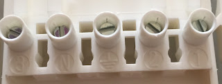
Take one side of the 5-way connector and have a close look.
You can see that each connector is numbered 1 to 3 with the centre connector
being labelled as the earth and the connector next to it marked N for neutral. It doesn’t really matter where you put the other 3 wires,
the only thing that matters is that you use the same number for the
same colour wire on both sides of the connection. So if you put the orange wire into number 1 on one side of the connector then you must put the orange wire into number 1 for the other side.
Step 4
Having wired up our loose cable we can now wire the cable
that comes with the new 3 port adapter into the other side of the connector.
Step 5
Just to be certain, push the 2 connectors together and check that the same colour wires are joining up. Note that the colours can vary a little,
one might be dark blue another might be light blue, but hue and tone aside the
basic colours should match up. When you’re sure, fit the cover over the
connector and use the 2 screws provided to secure the cable in place. Repeat
this for the other side of the connector.
Step 6
With the covers on, push the 2 connectors together. They are shaped
so that they can only fit together one way. Now switch on the electricity
and Bob should be your uncle


No comments:
Post a Comment